MPP Bypass Diode Power Optimizer vs Dynamic Peak
Each PV module has a so-called Maximum Power Point (MPP), the operating point at which the voltage used achieves maximum output. The data of the modules can be found in their data sheet.
Typical values in a data sheet could look something like this:
| Power Pmax | Open-circuit voltage (Voc) | Current Impp | Voltage Vmpp |
| 420 W | 48 V | 10 A | 42 V |
Where exactly is the MPP of a PV module?
The specified open-circuit voltage is also available in low light conditions. If the module is loaded by the inverter with a resistor, the voltage drops accordingly and the current increases. Under ideal conditions, the load corresponds to the MPP value of the module, according to the data sheet: Vmpp, in the example: 42V and the current: Impp, here 10A. If the inverter were to load the module more than the Vmpp value, its output would decrease again. According to the fictitious data sheet, at maximum solar irradiation and optimum ambient temperature, the module delivers at 42V: 10A, which means P = U * I: 42*10 = 420 Watt Pmax. Outside the optimum conditions, the voltage and current values deviate from the MPP values (Vmpp and Impp) specified in the data sheet. The task of an MPP tracker is therefore to determine the ideal operating point, the ideal voltage for maximum power and to operate the module in the best possible range.
So far so simple, but what if several modules are connected in series and the MPP of the individual modules is different due to shading or other influences?
Partial shading: power optimizer vs. dynamic peak manager vs. bypass diodes vs. microinverter?
In order to be able to deal better with partial shading, hoday PV panels have 3 bypass diodes that can deactivate parts of the module. By adjusting the string voltage, the diodes switch through and bypass the shaded area.
Since the inverter optimizes the MPP based on the total voltage of all modules connected in series, a panel with a different MPP could potentially affect the entire string.
When optimizing the strings, especially in the case of shading, I came across different optimization approaches during my research. Certain manufacturers, including Solar Edge, use so-called power optimizers for optimization: small additional devices under the respective panel, which determine the ideal MPP (Maximum Power Point) per panel and adjust the output voltage. In addition to the additional costs for the optimizers, the optimizers themselves also require some power, albeit not much.
As an alternative, Fronius advertises that its "Dynamic Peak Manager" does not require a power optimizer. The integrated shading management is described with an MPP tracking algorithm, which optimizes the yield at string level. The setting can be found under Device configuration, Inverter PV:

The principle behind the MPP tracking algorithm is that the inverter tests the power characteristic curve at regular intervals (every 10 minutes) and then sets the voltage that delivers the most power.
Can different PV modules be used in one string?
Finally, a consideration regarding the use of different modules in a string. If the modules used in a string have different currents: Impp, the modules with the lower current values would slow down the modules with a potentially higher current value. Different voltages, on the other hand, could be balanced out by the MPP tracker.
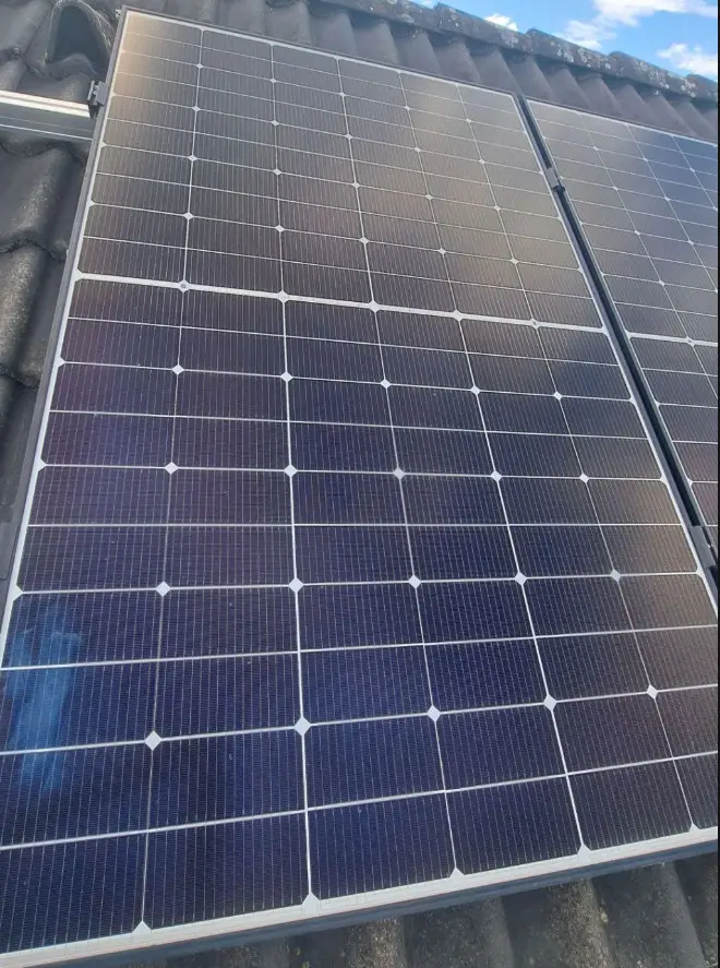
Bypass diode considerations Half-cell module
A module with partial or complete shading generates low currents and thus slows down the entire string. The bypass diodes counteract this: As the name suggests, these bypass zones with less current. To understand this, I have tried to understand the individual areas of a modern half-cell PV module and its zones, as well as the associated voltages and currents. The following examples do not take losses into account and are purely theoretical and correspond to my considerations. Here is the ideal operation, all cells are irradiated evenly and deliver the theoretically possible maximum:
Ideal operation and theory
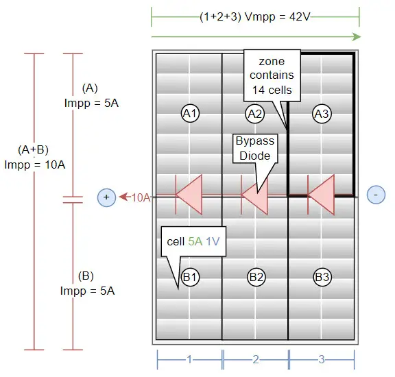
The schematic representation of a PV module and the partial voltages / currents shown.
 |
 |
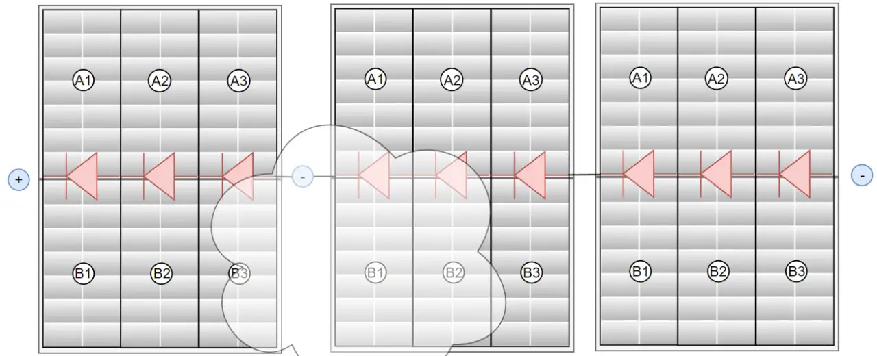
To explain: The fields within the PV modules are divided into 6 zones, here A1-3 and B1-3. Zones A and B are in parallel, the actual PV cells are within the zone and zones 1-3 are also connected in series. Under ideal conditions, the voltages of the series-connected cells add up while the current remains constant. Today's PV modules basically consist of two individual modules (A and B in the picture), which are connected in parallel. In a parallel connection, the current doubles: here 5 + 5A = 10A. The PV module shown here therefore supplies 10A (I) and 42V (U), which would correspond to an output of 420 watts (P=U*I).
Cells that are partially shaded deliver correspondingly less current under load than unshaded modules: What's more, the shaded cells are pulled along by the unshaded cells so that the current flow is maintained as much as possible, consuming the energy generated by the other cells in the zone by converting it into heat: The voltage of the shaded cell reverses until it exceeds the voltage of the unshaded modules. If the voltage exceeds 0.5V, the bypass diode is activated and the zone is bypassed. This illustrates what could happen if only one cell is completely covered:
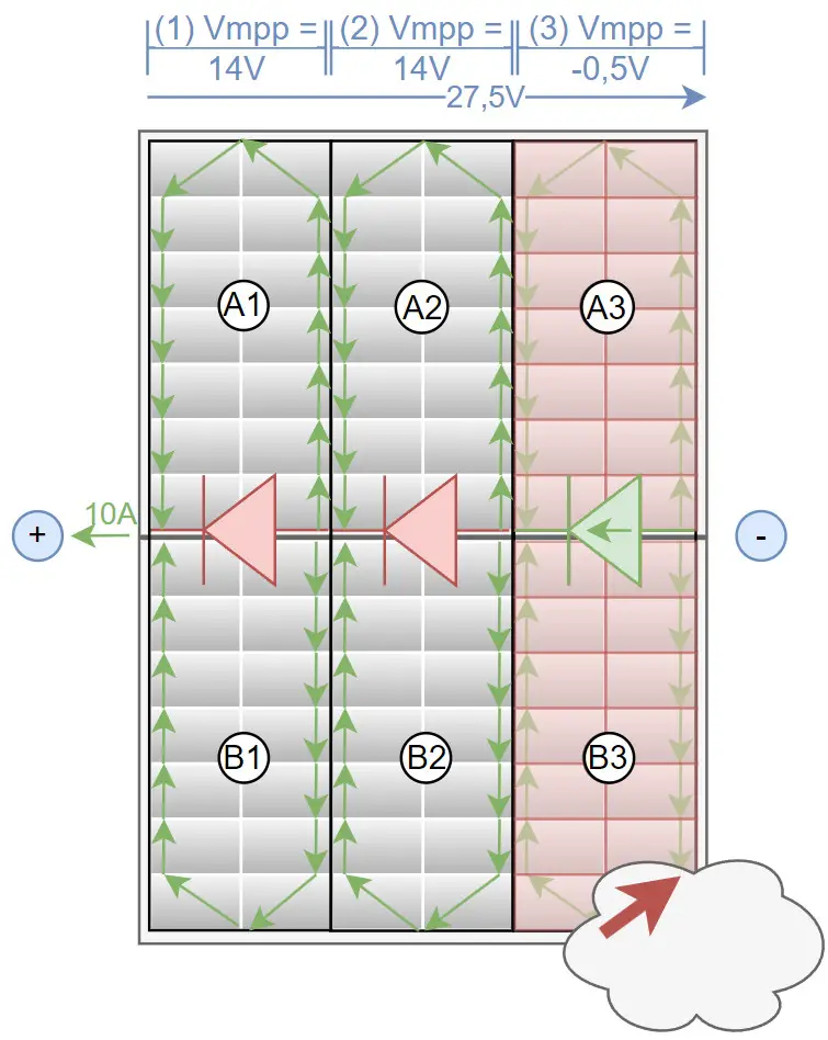
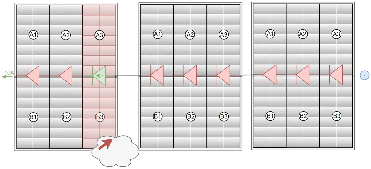
The bypass diodes also help to ensure that the shaded cells are bypassed before they overheat and are damaged in the process. As the bypass diodes only become active when sufficient current is flowing, it is important that the inverter reduces its MPP voltage accordingly. Since a PV module behaves internally like 3 modules connected in series, several modules in a string extend the circuit by additional zones, but the principle is similar to that of a single module and its zones:
Considerations and the effect of the shadow using a fictitious example
In reality, more or less partial shading occurs with several cells. For a better idea, I have considered what could happen if two of three PV modules connected in series are partially shaded and different voltages are used for operation.
Example 126 V => 504 Watt : Inverter uses the Vmpp voltage
In the first example, the inverter uses the voltage for 3 unshaded modules: Vmpp, none of the bypass diodes become active:
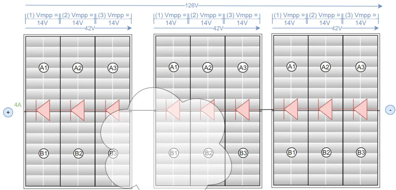
If the PV modules were unshaded, a voltage of 42V*3modules = 126V would correspond to Vmpp. Assuming that the shading in module 2 leads to the current being limited from 10A to 4A, the 3 modules would provide an output of 126V*4= 504Watt.
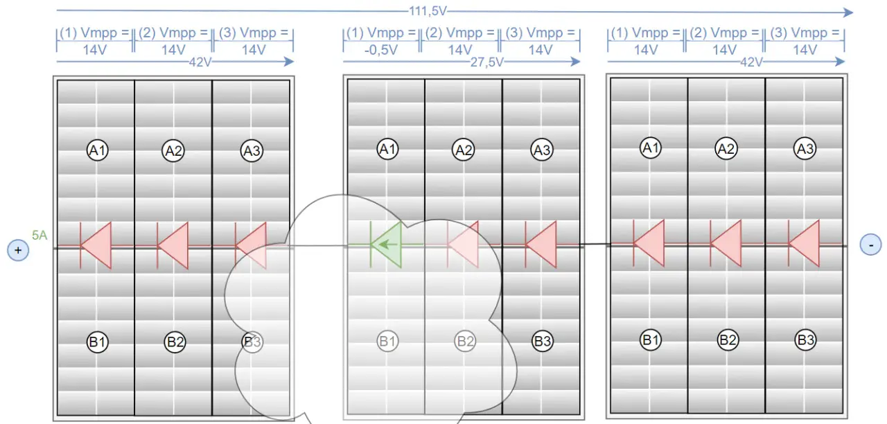
Example 111.5V => 557.5Watt
If the inverter regulates the voltage down by 14V to 111.5V, the bypass diode of the most shaded module could become active, which, purely assuming that the current could increase from 4A to 5A, would then be 557.5 watts.
Example 97V => 533.5 watts
A further reduction of the voltage to 97V could increase the current to 5.5A and reduce the power again to 533.5 watts.
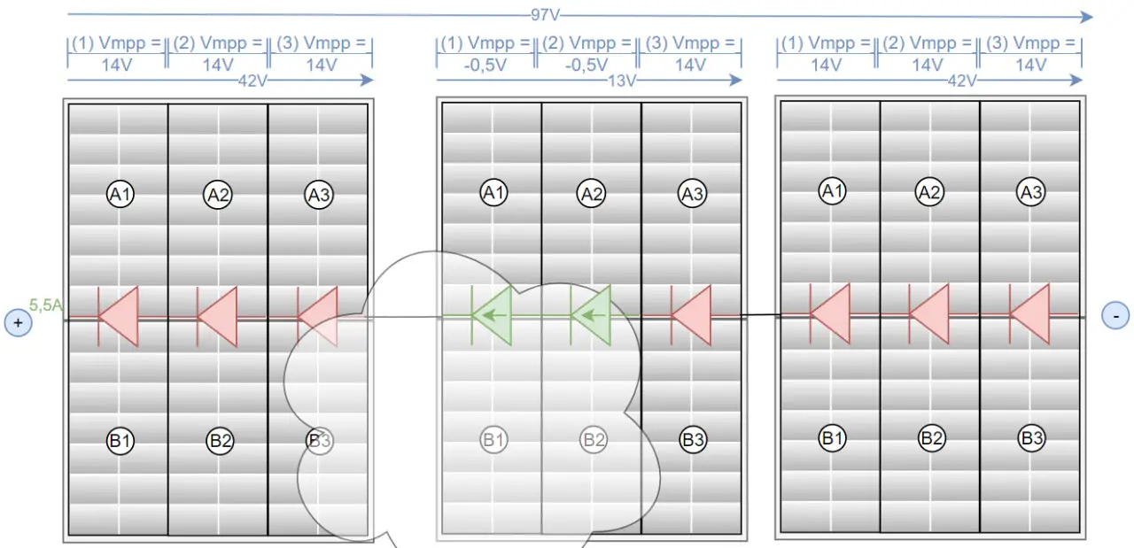
In this scenario, it is important that the inverter does not switch back to 111.5V, as a further reduction in voltage can deliver even more power:
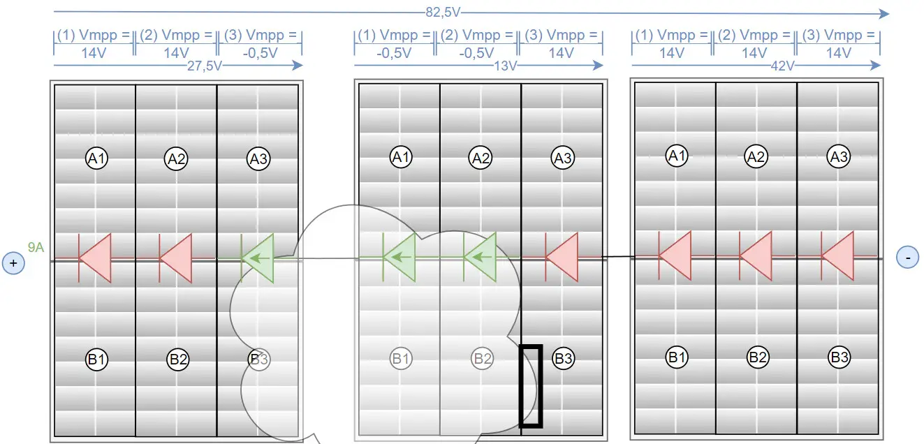
Example 82.5V => 742.5Watt
And even further down, to 82.5V, the current could recover to 9A as only a very small area in module 2 brakes, would then be 742.5 watts
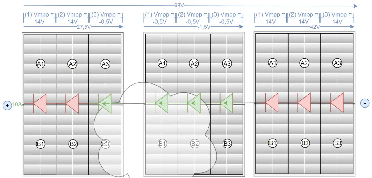
Example 68V => 680 watts
At 68V, module 2 could be completely deactivated, which would correspond to an output of 10 A * 68 V = 680 watts: too much of a good thing.
And when using performance optimizers?
When using power optimizers, each module could be regulated individually: In the previous examples, this would add up the best possible MPP values of the examples above:
| best variant | Output | |
| Module 1 |
27.5V * 10A |
275 watts |
| Module 2 | 42V * 4A | 168 watts |
| Module 3 | 42V * 10A | 420 watts |
| Total | 863 watts |
The calculation does not take into account any converter losses of the power optimizers, is purely fictitious and reflects purely assumed values and their considerations! Not only could other scenarios produce different results, but adjusting the values would also lead to different results: As an example, the advantage of power optimizers is put into perspective if additional unshaded modules are added to the string. This is purely about how it works.
Alternative microinverters?
Another alternative is the use of so-called micro-inverters, similar to the construction of several balcony power plants. For example, a microinverter could also be hung under each PV panel in larger systems, which means that each panel has its own MPP tracker. A central inverter would therefore no longer be necessary. In addition to the well-known manufacturers of inverters for balcony power plants, the manufacturer Enphase has focused on this concept especially for the use of larger systems. In contrast to a string inverter, micro inverters may have a higher level of self-consumption as the electronics for management are available multiple times. When using a storage unit (battery), the already converted alternating current must be converted back to direct current during the charging process, which means higher losses. It is also much more difficult to implement an emergency power function with microinverters.
Inspired by the following sources:
- photovoltaikbuero.de/pv-know-how-blog/teilverschattung-photovoltaikmodulen-teil-23/
- www.fronius.com/de-at/austria/solarenergie/installateure-partner/produkte-loesungen/features/dynamic-peak-manager.
- https://www.youtube.com/watch?v=5jjqmDXgSb4
Conclusion: Which is better now: power optimizers or just bypass diodes?
Contrary to what is often claimed, a little shade does not usually lead to the complete failure of the entire string. The influence of partial shading can be compensated for somewhat with the help of bypass diodes and by adjusting the MPPT voltage. From the considerations presented here, I would conclude that a string inverter cannot have such granular adjustment options purely via the bypass diodes of the PV modules as the use of power optimizers. Power optimizers also have better monitoring of individual PV modules. On the other hand, there are possible power losses of the optimizers in standby, when converting the voltage and the higher price, as well as additional components and plug connections on the roof that could potentially cause problems. In summary, I would not use power optimizers for light shading: A string inverter can compensate for individual areas very well. In my opinion, power optimizers only make sense if the PV modules are often partially shaded over a large area, e.g. by trees etc., or if the modules have to be installed at different tilt angles. ... See also: PV - Considerations - Planning - Implementation
 ({{pro_count}})
{{percentage}} % positive
 ({{con_count}})