3D Printer Caution Fire Hazard

The 3D printer as a potential cause of fire: I had read about this and also thought about it, but in the wrong place.
Caution: Fire hazard
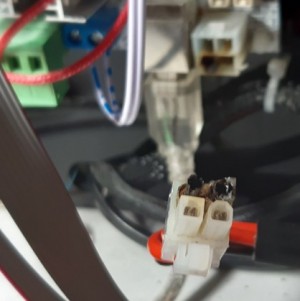
I would have always considered the MOSFET or the hotend as the cause of the fire, but in the case of my printer, a faulty contact during the power supply led to the socket and the plug being burned. The problem started slowly: sporadic dropouts and later the smell of burnt electronics, which I couldn't identify at first. From the outside it was hardly visible, but the cause was the power supply to the controller board:


After I found the issue, I soldered the cables directly to the controller board and installed an additional MOSFET, more about this below ...

the cause: low voltage, high currents
The fact is that especially the heater bed draws relatively high current at 12V. The printer's power supply delivers 12V and 15A, which corresponds to a power consumption of about 180 watts according to the specification. The measured power consumption of the printer is 121 watts in total, the power supply would theoretically still have some room here:

A multimeter between the contacts to the heat bed (MK2a Heatbeat) shows up to 9 amperes when switched on which results in more than 100Watt at 12V (12V*9A).

With more than 100 watts for the heat bed and a total power consumption of 121 watts there is not much left for the board itself and the heater nozzle. So most of the current runs through the controller board and a MOSFET to the heating bed.
MOSFET
Responsible for switching the heating bed and the heating nozzle are so called MOSFET. The complete current must pass through these power components, accordingly they become hot when controlling the heating bed. On my controller board, the GT2560, 3 MOSFET are installed, but by default only two are used: one for the heating nozzle (hotend), one for the heating bed, the third MOSFET would be for an optional second hotend:

An additional MOSFET can be installed to relieve the controller board and route most of the current past it:

The MOSFET gets power directly from the power supply with its own cable and is then controlled by the existing MOSFET. The existing MOSFET has an easy time of it, since it no longer has to carry a load.
A much more powerful component can be used as the MOSFET, which gets much less hot than the original MOSFET of the controller board..
Other printer improvements, see: Prusa i3 based printers: improvements and customizations
 ({{pro_count}})
{{percentage}} % positive
 ({{con_count}})
THANK YOU for your review!
Questions / Comments
(sorted by rating / date) [all comments (best rated first)]
Seems to be a general problem with the unsuitable plugs.
Nevertheless, using an external switching stage is a fool's errand. The FETs installed on the board are good for 50A, i.e. at 12V for a heating bed with a maximum of 500 watts (with some reserve), at 24V for 1000 watts (theoretically).
It makes much more sense to either solder the supply lines directly or to use proper connectors (XT60 for example). Then remove the paint from the two conductor tracks on the back of the board and reinforce the conductor tracks with a lot of solder and a piece of bare wire. It is also helpful to use thermal paste sparingly between the FET and the heat sinks.
Then there will no longer be any problems, even with thick heated beds...

But of course that's just my personal view of the matter...

Greetz
Micha aka CBX.Micha